Saturday, November 7, 2009
Friday, November 6, 2009


I believe Design Center is a very useful tool. With Design Center you can find and reuse layers, layouts, linetypes, dim styles, text styles, hatches and blocks from other drawings. Certain parts of a drawing can be copied into another drawing easily. Choose the parts in right side of dialog box. Drag and drop the parts into the drawing area of the dwg file that you have open. Blocks can be categorized and used in the tool palette. Make a library of blocks or hatches in tool palettes. Simply click on a block from Design Center and drag it over to a tool palette, drop it when the cursor is above the gray area of a tool palette. This feature in AutoCAD is great, because it makes your work easier and saves a lot of time!
The data from an AutoCAD drawing consumes the resources on a IT system. Therefore you must regularly remove unnecessary data from a drawing. You do this with the PURGE command. In older version before 2000 you have to write PURGE in command line, at the prompt "do you want to purge all objects? Type Yes, enter. In newer versions, you use a dialog box, selectively you choose what kind of objects you want to purge. Only use purge when the drawing is complete. Else you might remove layers or textstyles that you wanted to keep.
A command alias is an abbreviation that you enter at the command prompt instead of entering the entire command name.
For example, you can enter a instead of to start the ARC command. An alias is different from a keyboard shortcut, which is a combination of keystrokes, such as CTRL+N for NEW.
An alias can be defined for any AutoCAD command, device driver command, or external command. The second section of the acad.pgp file defines command aliases. You can change existing aliases or add new ones by editing acad.pgp in an ASCII text editor. To open the PGP file, Click Tools menu - Customize - Edit Program Parameters (acad.pgp). The file can also contain comment lines preceded by a semicolon (;).
Before you edit acad.pgp, it would be a good precaution to create a backup so that you can restore it later, if needed.
To define a command alias, add a line to the command alias section of the acad.pgp file using the following syntax:
abbreviation,*command
where abbreviation is the command alias that you enter at the Command prompt and command is the command being abbreviated. You must enter an asterisk (*) before the command name to identify the line as a command alias definition.
If you can enter a command transparently, you can also enter its alias transparently. When you enter the command alias, the full command name is displayed at the Command prompt and the command is executed.
You can create command aliases that include the special hyphen (-) prefix, that accesses a command that displays a command prompt instead of a dialog box. Exclude the prefix (-) and you see a dialog box when you enter the command alias, surely only for those commands where a dialog box is accessible.
BH, *-BHATCH
BD, *-BOUNDARY
Note: You can't use command aliases in command scripts. It is not recommended to use command aliases in customization files.
If you edit acad.pgp while AutoCAD is running, enter reinit to use the revised file.
The drawing limits are there for a reason. When you start a new drawing, then decide how much space do I need for my drawing. Think of it as the size of your drawing area. Then you can define drawing limits correctly. Type LIMITS enter. Type 0, 0 as lower left corner then type or click the coordinate for upper right corner.
Furthermore, the drawing limits defines the extent of ZOOM all. Tip: You can make a little space around the drawing frame, if you define drawing limits a inch outside the drawing frame. This makes it easier to do PLOT "window".
There are certain benefits when you use 3D solids. From 3D solids you can read mass, volume, centroid, moments of inertia, products of inertia with the MASSPROP command. This information is not possible to get with a box build with surfaces. The exception here are regions. From these you can read area, centroid, moments of inertia and product of inertia. And it's easy to edit a solid with grips. Moreover, you can easily create holes, fillets and chamfers on a 3D solid. Additionally, you can use boolean operations on solids, like intersect, subtract and union. My advice: Always use 3D solids or regions, when it's possible in AutoCAD. In architectural design, use region for the floor. Because it's easier to get the area with the Massprop command.
Type OPTIONS enter, click on System, then click on Performance Settings. Click on the small "check box" Adaptive degradation, so that it's ON. Next "check" all items below. In the dialog box "Adaptive Degradation and Performance Tuning" click Manual Tune. Next "check" to enable hardware acceleration and reset to recommended values, continue clicking OK, until you have exited all dialog boxes.
To save time only render a preview in smaller output size 640 X 480. When making previews you can also use "render cropped region". Only use shadows, in final render. Use ray-traced reflections and refractions, when it is needed, namely in scenes with water, marble, glass and mirrors. Shadow mapping display more soft edges and require less rendering time. Ray-traced shadows have more accurate and hard edges. The ray-traced shadows also transmit color from transparent and translucent objects. However this shadow setting require more rendering time. Use only 1 or 2 lights in a scene. The excepting is indoor interior, where is many lamps and spotlights. Only use sunlight in a outdoor scene. If using sunlight, then adjust light intensity, time and date depending on the atmosphere you want to set. Use the necessary time to adjust falloff angle in cone of spotlight, light intensity and the angle from light source to target. Some scenery require that you combine point light with spotlight
Creating 3D wireframe models can be more challenging than creating 2D drawings. Here are some advice that will help you work more effectively:
Create sufficient layers to organize your model. Turn off layers that you currently are not working with. That way you reduce the visual complexity of the model. Use different colors can help you differentiate between objects in various views.
Create construction geometry to define the basic envelope of the model.
Create and use multiple views, especially isometric views. Hence making visualization of the model easier. Additionally it becomes easier to select objects.
Become familiar with the User Coordinate System - UCS. Learn how to make the XY plane in UCS parallel with another plane. Learn that Z is the depth in 3D space. The XY plane of the current UCS operates as a work plane to orient planar objects such as rectangles, circles and arcs. The UCS determines the plane of operation for moving, trimming and extending, offsetting, and rotating objects.
Always use object snaps and snap, this will ensure the precision of your model.
Use coordinate filters to easily locate points in 3D based on the location of points on other objects


A long time missed feature in AutoCAD has finally arrived. It is the command SECTIONPLANE. For example to make a cross section view of a house. I will explain you the most easy way to do this. Type sectionplane in the command line, followed by enter.
Then chose


With the LOFT command, you can create a new solid or surface by specifying a series of cross sections. The cross sections define the profile (shape) of the resulting solid or surface. It is recommend to use
First you create 3 splines, next you select them as cross-sections in order from A to C
From AutoCAD 2007 a brilliant new 3D command arrived. It's called Presspull. If you have made a 3D box and want to make a hole through you can do that with PRESSPULL. First you create a rectangle with a polyline on top of 1 face on the 3D box. Next you activate PRESSPULL command and click inside the rectangle. Now you can make a hole by pulling the face on the rectangle inside the box. You can use this command for the existing faces of an object, or by imprinting additional faces on an object and pulling those inside or outside. If you pull it outside of the box, then you create a solid object pointing out from the 3D box. You can also use 3D POLYLINE instead of polyline. First align UCS so it's parallel with the side you are making a hole. Scroll down on this page to see tutorial "Creating a Wall with Polysolid".

In AutoCAD 2007 and later 2008 it is possible to select the face behind. For example on a 3D box that would be the face on the backside. Procedure: Place the pickbox on the front face, next press down CTRL, while pressing down CTRL you hit the spacebar once and you see that the face on the back side is selected. Don't click on any faces before AutoCAD has selected the face. It's essential that you place the pickbox virtually on the face behind before you hit the spacebar, see image below. You can also select the other faces using the same procedure.
Use the tool palettes as organized menus. Place them on the right side, if you are right-handed. Add your favorite commands, dimstyles, textstyles, hatches, blocks and materials on tool palettes. Save time by creating a library of blocks and dynamic blocks. On the tool palette you can use autohide, if you want more space on the screen. I recommend the following: Right-click in the bigger gray area on tool palette. Next click "Sort By Name", this will display you list in alphabetic order. In the same shortcut menu, adjust the size of images and text in "View Options". Furthermore, I recommend that you move all tool palettes into palette groups. This way the tool palettes are organized and it is easier to find them. Again right-click in the bigger gray area on a tool palette, now click Customize Palettes. In the dialog box, move all the tool palettes from the left side into palette groups on right side.
Use the RAY command instead of XLINE command. Besides creating basic construction lines, it also will create lines at precise angles fast and easy. Use the RAY command with osnap "on" when you make your projections. Tip: After trimming, the ray lines becomes lines. The RAY command never extend the line in 2 directions. The line is extended infinite, but only in one direction from the start point. Advantage: Not wasting time cutting construction lines at both ends. It will save you time, once you get used to the command
Formerly in older AutoCAD releases, when you used Polyline Edit to join a line or arc with other objects, you were prompted to enter Y (for Yes) if you wanted to convert the line or arc into a polyline. By setting the PEDITACCEPT system variable to 1, you can avoid this prompt and proceed directly to joining your line or arc with other objects.
From AutoCAD 2006 you can use Pedit to convert multiple lines or arcs to polylines in one session. This option will save you a lot of time, if there is many lines in the drawing that needs to be converted. Type PEDIT enter. Type M for multiple, choose the lines you want to convert. To the prompt:
XPLODE is a very good command that allows you to control the color, layer, lineweight and linetype in all the components of an exploded object. It works similarly to EXPLODE, but with more functionality. For example, a block is a compound object. You can explode multiple compound objects simultaneusly. Furthermore it's possible to change the color, layer, lineweight, and linetype of each object individually or change the entire selection set globally. You can specify a color, layer, lineweight, and linetype, or these properties can be inherited from the object being exploded. A compound object contains multiple AutoCAD objects. Xplode breaks a compound object into its component objects.
I find the STRETCH command to be very useful, when you edit objects. With this command it is easy to change the dimensions of multiple lines, a rectangle or triangle. Use a crossing polygon by typing CP to select multiple objects, then stretch them to a desired location. When specifying second point: I moved the mouse in the desired direction, then type the distance and press enter. Remember, ORTHO must be on. If you wan't to do a diagonal stretch, then use Polar Tracking. Procedure: Press F10, then right click on Polar Tracking in the status bar, next click "settings". Set increment angle to a specific angle. Now do the stretch command as described above.
From AutoCAD 2006 a new feature in AutoCAD has appeared. In the TRIM command you can switch to extend by holding down SHIFT, you select the objects first and then press down shift while you click on the end of a line you wanna extend. You can do the same with Extend command, switch to Trim. But there are also more functionality in these 2 commands. Especially the options Fence and Edge are worth mentioning. With fence at hand you can easily trim or extend multiple lines by making a long cutting line in 2 clicks! The other option I should mention is Edge. With Edge you can extend to a invisible boundary. There should bea line to make an invisible extension with. Select the option Edge in the Extend command. When AutoCAD prompt; "Enter an implied edge extension mode [Extend/No extend]
While viewing a layout, did you ever want to make a little change to your model without having to switch to model space? Did you ever start to make such a change, only to accidentally mess up the scale and limits of your viewport? Well, you can edit your models within paperspace viewports safely and easily with VPMAX.
In a layout with the desired viewport selected, click on the Maximize Viewport button at the bottom of the AutoCAD screen in the tools tray. Your viewport will switch to model space and expand to fill the AutoCAD screen. You can now safely edit, zoom, and pan without fear of ruining your carefully set up scale and limits. When you’re done editing, simply toggle the Maximize Viewport button again. All of your viewport settings are restored to normal and you’re ready to print.
Modelspace viewports in layouts are usually scaled at other than 1:1 ratios. This means that text objects in the viewport may appear at a different size than on the layout, even if they have the same height property. The SPACETRANS command changes distances (typically text heights) from either modelspace or paperspace to an equivalent distance in the other space. This command can be invoked transparently to provide correct values when distances are requested by other commands. If used in standalone mode, this command displays the computed value on the command line.
Ever get frustrated trying to draw an arc clockwise as opposed to the default counter-clockwise? Try this to draw an arc using ""end-center-end"". Draw a ""V"" shape using equal line segments. Before you start drawing the arc bring up the UCS tool bar and rotate around the X or Y axis 180 degrees. Now draw the arc using the left point of the V as the start point, the vertex as the center, and finally the right point of the V to end. Don't forget to select the ""world"" icon on the UCS tool bar to return it to normal.
From AutoCAD 2006 Autodesk introduced dynamic input, this display your coordinates and angle input on-screen in small boxes. The standard setting for this feature creates a little problem, when you type absolute coordinates. The solution is to switch off dynamic input, before you type the coordinates. Just press F12 and you can type the coordinates in the command line.
Use object snap tracking to track along alignment paths that are based on object snap points. Acquired points display a small plus sign (+), and you can acquire up to seven tracking points at a time. After you acquire a point, horizontal, vertical, or polar alignment paths relative to the point are displayed as you move the cursor over their drawing paths. For example, you can select a point along a path based on an object endpoint or midpoint or an intersection between objects.
In the following illustration, the Endpoint object snap is on. You start a line by clicking its start point (1), move the cursor over another line's endpoint (2) to acquire it, and then move the cursor along the horizontal alignment path to locate the endpoint you want for the line you are drawing (3).
You probably received a drawing that was scaled wrong. I recommend using this method to change the drawing into a correct scale.
Type SCALE enter.
Select objects.
Select a basepoint, choose lower left corner.
Select Reference enter.
Select 2 points that defines the total length of the object.
Now enter the correct length.
When you want to copy objects, simply use "COPY TO CLIPBOARD", instead of using the command "COPY WITH A BASE POINT". It lets you pick a base point on the DWG to copy from. Then the basepoint will be used as a insertion point, when you insert a block, then you can specify the exact position. Even try creating a tool bar button for the command.
A fast method to begin a drawing such as a floor plan is to use the RECTANG command to create a series of overlapping walls. Use the REGION command to convert them to regions and then use UNION and SUBTRACT to join them together. Now everything should look neat, without any overlapping. Finally, to turn the objects into lines, use the EXPLODE command
Click on the 'erase' icon twice with the right hand mouse button.
This will display Button Properties.The Macro command line should read - ^C^C_eraseChange this line to read - *^C^C_erase single. So when you erase objects, just click on them and they will disappear at once.No need to confirm each selection with the right mouse button. You can apply this little coding trick to all the editing commands. I think it's a great way to speed up your work.
Select the objects to copy.
Select a base grip on an 2D object by clicking the grip. The selected grip is highlighted (turns red), and the default grip mode, Stretch, is active.
Cycle through the grip modes by pressing ENTER until the grip mode you want appears (stretch, move, rotate, or scale). Choose rotate. Alternatively, you can right-click to display shortcut menu modes and options.
Next choose a basepoint.
Enter C (Copy).
Now you can make copies of your object, for example around a circle, by pointing some angles with polar tracking. Copies continue being made until you turn off grips.
Turn off grips by pressing SPACEBAR or ESC
Let's say you want to create a circular viewport completely contained within a larger rectangular one. You don’t want objects displayed in the rectangular viewport, only showing objects in a circular viewport.
Here is what you can do:
In a layout viewport, create a rectangle and a circle within it.
Create a copy of the circle in the same location as the original circle (use COPY 0,0).
Change all three objects into regions with the REGION command.
Subtract one of the circular regions from the rectangular one with the SUBTRACT command.
Enter the MVIEW command and specify the Object option. Select the rectangular region, change it into a viewport with a "hole" in it.
Repeat the MVIEW command selecting the remaining circular region. This converts it into a separate circular viewport, that fills the hole in the previous one
Tuesday, November 3, 2009
AutoCAD Virus Alert
CAD Manager's Toolbox: A self-replicating virus is on the loose that masquerades as the ACAD.VLX or LOGO.GIF file.
We CAD users have, for the most part, been less bothered by virus problems than other users in the past. It seems like Microsoft Office documents and picture files that have been the purveyors of doom in the past. No more, it seems.
AutoCAD users should be aware of a self-replicating virus that masquerades as the ACAD.VLX or LOGO.GIF file. The mode of infiltration is an ACAD.VLX file introduced into a folder full of DWG files and/or a support path that allows the file to load upon AutoCAD's startup. After initial infection, the ACAD.VLX file is copied as LOGO.GIF into AutoCAD's help folder where it lies in wait for further file openings.
The virus appears to modify system startup files using an ingenious Visual LISP copy string that spells out the name of the file in ASCII integer values so as to escape detection by all but the keenest programmers. The payload of the virus seems to be file modification that causes error dialogs denoted by missing language support files upon subsequent opening of infected DWG files.
CAD managers who have AutoCAD-based platforms should perform the following steps to avoid infection:
- Scan for the presence of ACAD.VLX and LOGO.GIF files on user machines.
- Scan for the presence of ACAD.VLX on all network volumes.
- If the above files are found, take steps to delete the files and implement cleanup procedures using this link: http://usa.autodesk.com/adsk/servlet/ps/dl/item?siteID=123112&id=13717811&linkID=9240617
- Be sure to find all instances of the modified ACETAUTO.LSP, AI_UTILS.LSP, and ACAD.MNL files (critical to stop the spread of the virus) referenced in the document above.
Please note that ACAD.VLX and LOGO.GIF are not native AutoCAD files, so unless you've created custom routines that use these files their presence most likely denotes infection. The virus to date is not common and appears to be relatively harmless — but why take chances?
Autocad Layer Properties Per Viewport
For the past couple weeks The CAD Geek Blog has been rather quiet. Rest assured I haven’t abandoned my little corner of the CAD blogosphere, but rather took a little end-of-year vacation (Dec 17-Jan 1). I started my vacation with grand plans of blogging almost non-stop, and finding new ways to break AutoCAD and Civil 3D. What actually happened was a lot of Christmas shopping, followed by a number of excursions.
Proclaimed as the birthplace of the Tacky Christmas Light Tour, I had a chance to visit the many tacky homes in and around Richmond, VA. My mothers home is among those on the Richmond Tacky Light Tour. Getting Christmas off to a somewhat comical start was me attempting to calculate and balance the electrical load for her light display. 2-30 Amp and 2-20 Amp breakers later – we had lights!
Other highlights of my long Christmas break included visiting Baltimore, MD for their Miracle on 34th Street; Newport News, VA for their Celebration in Lights, and Virginia Beach, VA for their Holiday Lights on the Boardwalk. Finally I had the pleasure of bringing in the new year with my favorite band – Carbon Leaf. Needless to say, all that fun didn’t leave much time for blogging. But 2008 is here, and so am I!
AutoCAD 2008 introduced a handy feature for managing layers properties on a viewport-by-viewport basis. Pre-2008 we could only freeze and thaw per viewport, but now we can change Color, Linetype, Lineweight, and Plot Style. In the short time we have had 2008 installed, the feature has already proven helpful a number of times. So just how does one use this feature?
Below is a quick look at the Layer Properties Manager when clicked into a viewport. You’ll notice the additional columns to the right. Each of the columns prefixed with a "VP" can be overridden on a viewport-by-viewport basis. That means you can display the same layer with two different linetypes in adjoining viewports.
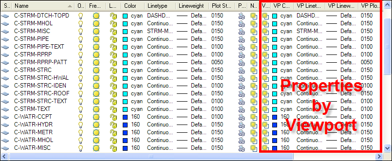
By default the Color and VP Color columns are the same, Linetype and VP Linetype the same, etc… With any viewport active you can open the layer properties manager, modifying its display properties in only that viewport.
So let’s say I change the color of my Storm Pipe Text layer C-STRM-PIPE-TEXT from Cyan to Magenta.
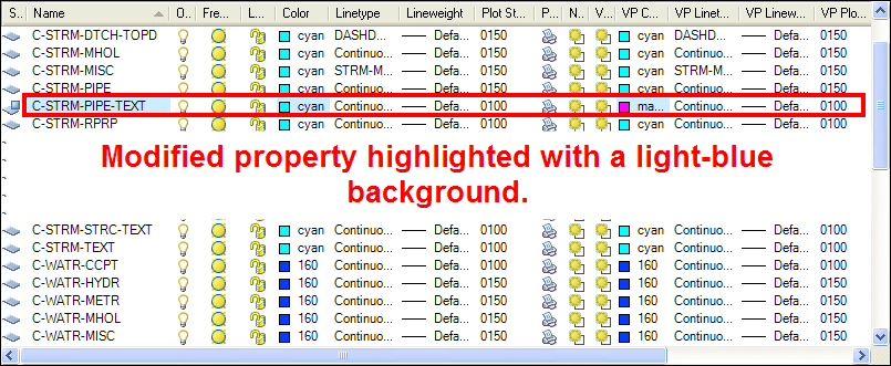
Notice when I change the VP Color column from Cyan (it’s default) to Magenta, the Name, Color, and VP Color columns are highlighted with a light-blue background. This is a visual cue letting you know the color has been overridden for that viewport.
While changing layer properties within a single viewport may be pretty straightforward for many, what about resetting things back to their defaults? Assuming you are an hourly employee you could always look at each layer, insuring the overall drawing properties match the VP properties, but certainly there’s a better way!?!
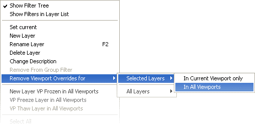
Funny you should ask – there is indeed a better way. Right-clicking on a given layer will give you the option to "Remove Viewport Overrides for" either "Selected Layers" or "All Layers". Finally you are given the option to reset either your selected layers or all layers "In the Current Viewport Only", or not only the current viewport, but rather "All Viewports".
AutoCAD 2008: CommandComplete:
It's a new year and many are back to work—some are still in the holiday mood while others are moving busily ahead with their regular work. As for me, I'm going to start writing slowly and gain momentum later. 
In this article, I’ll focus on a tool developed at Autodesk Labs and related to AutoCAD called CommandComplete Bonus Tool.
With ever-increasing software capabilities, the number of tools and commands is increasing as well. This leads to various problems such as how to remember all these tools! If there is a method by which you can identify them easily, then as a software developer you have satisfied your customer base. This is exactly what Autodesk has done with CommandComplete, which provides easy access to more than 1,400 commands and system variables. Sound interesting? Let’s get started.
Step 1: Visit Autodesk Labs and select the option CommandComplete from the Utilities list or from under the Technologies drop-down menu.
Step 2: Click on Download. Read the Autodesk Labs Terms of Use. Click on Download at the bottom of this page.
Step 3: Once you are done with step 2, extract the zip file which includes a folder named Command Complete.
- AsdkCommandComplete (arx file)
- AsdkCommandComplete_64 (arx file)
- Commandcomplete (xml file)
- Read_Me_First (txt file)
The extensions arx is Object Arx and xml – Extensible Mark up Language.
Step 4: Open AutoCAD 2008/2007 and click on the tools menu bar and select load application, as shown in Figure 1.

Figure 1
Step 5: You will be prompted to select the file AsdkCommandComplete.arx file as shown below. If you are using 64 bit, then choose AsdkCommandComplete_64.arx.

Figure 2
Step 6: Once you have selected the file and clicked on load, the CommandComplete module will be initiated in AutoCAD. Alternatively you can load the file by typing appload from the command prompt.
Step 7: To automatically load the application, you may add the file to Appload Startup Suite or create an acad.rx file and add the file name in it, as shown in Figure 3.

Figure 3
Step 8: Now right-click on the GUI area in AutoCAD to open the command complete tool, as shown in Figure 4.

Figure 4
Step 9: Now as the user starts typing in the command prompt, a popup list appears displaying the list of commands and sysvars that match the input, as shown in Figure 5.

Figure 5
Step 10: There are different ways by which the user can search for a command as listed below:
- Start with user typed string
- Anywhere search
- Keyword search
You can activate or deactivate the CommandComplete tool from the AutoCAD context menu -> CommandComplete Options.
Note: The CommandComplete options menu is added to the AutoCAD default context menu. The CommandComplete Options are listed below:
- Enable CComplete – Turns the CommandComplete utility on or off.
- Enable Tooltips – Turns CommandComplete Tooltips on or off.
- Commands – Include or exclude commands from the CommandComplete list.
- System Variables – Include or exclude system variables from the CommandComplete list.
Step 11: CommandComplete helps you to alter the standard AutoCAD keyboard behavior in a simple way. You can use the UP and DOWN arrow keys to scroll the list and TAB or double-click on the list to use the selected command. CTRL + SPACE can be used to display the complete list of commands.
Step 12: The command complete uses the commandcomplete.xml file. This file can be edited in any standard editor like Notepad or WordPad to add custom text or tool tip information. The standard format of the .xml file is shown below.
---------------------------------------
---------------------------------------
Note: You can edit these command lines to display as required.
- id – Identification number of the command in the list.
- displayname – Name of the command as displayed in the auto-complete list.
- commandstring – Search string used to search for the command.
- tooltip – Tooltip to be displayed for the command (The value of sysvar is also displayed if it is a sysvar).
- keywords – Additional string that can optionally be included in the CommandComplete search.
- sysvar – Identifier to know if it is a system variable. Set to “1” for a sysvar, otherwise to “0."
Friday, October 30, 2009
AutoCAD Electrical
AutoCAD Electrical
Coinciding with the acquisition of VIA Development, Nate joined Autodesk in March of 2003 after a decade stint as an entrepreneur following a two-decade stint as a controls engineer and software applications developer at Owens-Corning. Nate is now the lead product architect for AutoCAD Electrical. He loves this stuff.